Alright, it's starting to look like a 3D printer :-) Now, let's give it a brain.

This post will be about the electronics of my franken-smartrap. I managed to take videos but I will highlight the issues I've had.
The parts:
Arduino MEGA - The part that runs the software (firmware) and controls all the components.


Stepper Drivers - The part that helps drive the stepper motors


When I first ordered the parts, I didn't know there were different boards that are being used for 3D printers. I believe the latest version is the Duet which combines the Arduino and RAMPS board with a chip that runs linux. As a beginner, I followed the smartrap design and ordered the RAMPS board.
Putting them together:
I couldn't believe it took some effort to find information online about how to put these parts together. Most articles I've seen just assume that everyone knows how so here are some watch outs for those building their first printers:
- I know you're excited to see your printer come alive but it helps to know what you're doing. I fried a few components as I was trying to make it move and it was only then that I searched for the documentation of the RAMPS board. As they say, if everything else fails, read the manual :-). If you're the adventurous type and likes learning the hard way, make sure you have a few spare parts. Otherwise, make sure you understand what's on this page.
- Make sure the jumpers on the RAMPS board are set the way you want it before installing the stepper drivers. Mine came without the jumpers installed and I spent a lot of time figuring out why the motors are not running the way they should. The jumpers under the stepper drivers controls the microstepping of the motors. In my case, they were set such that the X, Y, and Z motors are 1/16 but I left the extruder to be at 1/8 micro-step to give it more torque.

- If you're going to mess around with the stepper driver potentiometers, you should know that even if you could turn it around 360 degrees, there is a dead zone. They seem to be set right in the middle by default and you won't need to adjust them for X, Y and Z. I only needed to adjust the potentiometer for the extruder motor. Don't overdo it because you will cause your motor to overheat. I think this is how I fried one of my stepper drivers. Luckily I ordered a spare. One way of increasing the torque is by reducing the micro-steps so you might want to try that, too.

- DO NOT try to jog the motors without connecting the RAMPS to a 12V supply. I believe this was how I fried the 5V regulator on my Arduino board. Good thing there are different ways to power the arduino and I managed to avoid throwing the whole thing. Since the 5V regulator is busted, I can no longer power it directly from the 12V supply from the RAMPS board. My only options are either to replace the voltage regulator, power it through USB, or power it with 5V directly to pin Vin/Vcc. Since I planned on using ATX power supply, I can get a regulated 5V to power the arduino. But before this could be done, I had to cut the D1 diode on the RAMPS board so as to cut the 12V supply going to the arduino.
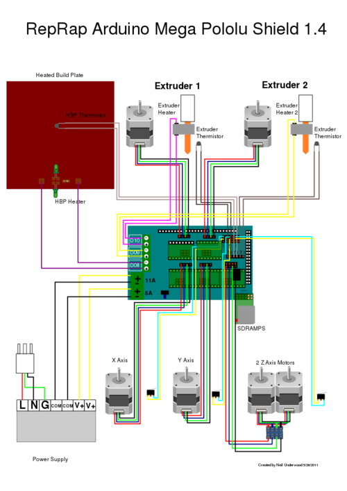
Now that I got over those quirks, wiring them up is a little more straightforward. This image from RepRap says it all:
To make it easy to follow this series, the links are here:
good post/
ReplyDelete