Showing posts with label 3D. Show all posts

Tuesday, May 13, 2014

Building my Repstrap Smartrap 3D Printer... and the setbacks (Part 4)

Before I can do a test print, I needed a glass of course.  I had a headed build plate but it's a little warped and arching in the middle. And I don't think I was supposed to print directly on it. I looked around the house and found an unused picture frame!  :)  I took out the glass and it fits perfectly with the length of my rods. Even if it's just 1/16 inch thick, it will do for now. When I installed it in the printer, the glass gives and bends a little during probing but not enough for it to break.

By this time, I have already gotten over some printing issues through trial and error. But not without some frustrations.  I agree that 3D printing is not for everyone because it takes a lot of troubleshooting before and during each print. One variable you change and your print will turn out differently.

Slicer Software 

Commercial printers come with the software you need to print but if you're just building from scratch reprap style, there are alternatives. You will primarily need a slicer - as the name suggests, it slices your 3D models into layers depending on the setting you provided and gives out a set of instructions for the printer to follow.  The settings can be overwhelming at first but when you get the hang of it, you will know which ones you need to adjust for every model you print. There could be times when you will forget to change something and only realize it after the print has already started. Sometimes, it would be okay to continue but there are times when you really need to stop the print and start over with the new gcode.

The first slicer I tried was slic3r but after using is for a while, I find it too slow so I tried Cura. Cura's user interface is better in the sense that you can visualize the gcodes and make adjustments immediately.  Unlike when I was using slic3r, I used to open the generated gcode file in repetier just to see if everything looks right before I print it out.


Semi-automatic bed probing


After assembly of the printer, the first problem I had was how to get servo to work. I tried to follow the guide and traced where the wires go. The RAMPS board has pins dedicated to servos but for smartrap, the servo wires go to the end stop max of z axis. I double and triple checked but the servo still doesn't work.

I happen to have a spare arduino uno board so I hooked up the servo with the sample servo sketch and still didn't work. I probably got a broken part. I am not willing to send it back to the seller in the U.S. so I needed to think of a way to manually or semi-automatically probe the bed.

My solution was to manually put the servo arm before probing the bed and remove it after the probing sequence.  To do this, I modified the slic3r start gcode so that after probing the bed, it will raise the nozzle 10mm and pause for 5 seconds.  This gave me enough time to remove the arm from the servo before it prints. It took took some effort but It works. I did this until I was able to print the parts for the mount without a servo.

Edit:
Here's how bed leveling is currently done on my smartrap with a broken servo


Z offset setting


Alright, it probes the bed, but when it prints, the nozzle was more than 5mm away from the glass. The filament comes out so I was sure it was just an adjustment somewhere. Turns out, there was a setting on the firmware to set the offset between the tip of the nozzle and the probe. X and Y were easy but I found it difficult to get the Z offset right and I didn't want to keep uploading the firmware whenever I change the value so another way to adjust the Z offset was through the slicer software. Different slicers have different ways of dealing with this.  Slic3r's Z offset setting is straightforward.  But in Cura, the only way I was able to adjust the offset was to modify the start gcode using the G92 command.

Getting the Z offset right needed a lot of patience and took a lot of trial and error. But when you get it right, you won't need to change it until you take your printer apart or make some adjustments that will affect the z offset.

First print issues


The first thing I wanted to print was the shaft adapter for the X motor. I got those motors with D shaped shaft but a little short especially on the X axis. This is the first successful print of the adapter.


Filament flow rate


I had the issue of the extruder motor springing back once in a while during a print. I thought the extruder was having a hard time pushing the filament because the nozzle was too cold. After some trial and error, the best thing to do in this case is to dial down the feed rate. It springs back because the extruder is giving too much filament than what can come out of the nozzle.


Print speed


No matter what I do, I couldn't print at speeds more than 20mm/sec reliably.  I guess that's just the limitation of my hotend nozzle and the heater element that came with it. If I go just about 1mm/sec faster, the heater could not keep up and the temperature quickly cools down.


Temperature


The suggested temperature for PLA was between 180 to 200 degrees but I just couldn't go lower than 230 degrees. At 220 degrees, it can still print slower but it comes out rough so I have to set it at 230.  I sometimes went too far and set it at 240 degrees.  I believe I stressed the heater too much because after just a few prints, the resistor broke.=(  I ordered the 30W heater cartridge but it will take a month to arrive. I will find fix but that will be for another post.

Right now, at least I know I can print! :)

To make it easy to follow this series, the links are here:

Thursday, May 8, 2014

Building my Repstrap Smartrap 3D Printer... and the setbacks (Part 3)

ATX Power supply to power my Smartrap 3D printer


I think there are a lot of advantages buying a complete kit when you get your first 3D printer. It will be less expensive and you will not have problems with incompatible parts as opposed to buying individual parts from all over the place (unless you can source all the parts exactly as in the BOM). You will also be able to start printing faster.  At least until you get it working reliably, you can start customizing and improving it which is not how it went for me.In my case, the customization part comes during the build since I was trying to make parts work together (again, this is because I can't source the exact parts in the BOM).

When it comes to power supply, things went smoothly.  There's a huge difference in price between the ATX and the industrial 12V power supply so I went for the ATX.  The instructions on how to use it for a 3D printer are also straightforward but unlike most people, I saved the 5V and 3.3V supply wires. I already mentioned that my Arduino Mega had a busted voltage regulator and that's what I need the 5V supply for. Then I plan to use the 3.3V supply to power some LEDs to light my build area.

I got one that is 700W. Should be more than enough for the 3D printer even for a heated bed. 
700W ATX power supply
Before I got cutting the wires and lose the warranty, it's good to test it first, of course.  I used a small piece of wire to connect the green wire to the ground wire to turn it on.
Yup, it turns on. :p  But what about the voltages?
So far, so good.  Time to open it.
All that's needed was to cut the wires coming out. They are color coded so I just combined the wires of the same color.  There were more ground wires so I bunched them into two just in case I find a need for it later on.
Finally, I used 16 gauge wire and soldered it to the 12V wires and the ground wire. The other end will go to the RAMPS board.

Improvement


The power supply is working great but after using it for a few days, I found myself always unplugging it from the mains when I needed to restart the printer. So I added a small switch which is what I should have done the first time =).

I used the same green and black wires I connected when I tested the power supply and soldered them to the switch.  Then I drilled a hole for it to go through.

Whohoooo! This part was the smoothest part of my build so far.  Time to try and print! :)

To make it easy to follow this series, the links are here:

Sunday, May 4, 2014

Building my Repstrap Smartrap 3D Printer... and the setbacks (Part 2)


Alright, it's starting to look like a 3D printer :-) Now, let's give it a brain.


This post will be about the electronics of my franken-smartrap.  I managed to take videos but I will highlight the issues I've had.

The parts:

Arduino MEGA - The part that runs the software (firmware) and controls all the components.
 RAMPS 1.4 - A shield (sort of an adapter) designed to connect all the 3D printer components like motors, temperature sensors, fans, heaters, etc. to the Arduino board.
Stepper Drivers - The part that helps drive the stepper motors 
 RAMPS LCD with SD socket - An input/output device allowing you to see the current status of the printer and allows you to print from SD card without USB connection.


When I first ordered the parts, I didn't know there were different boards that are being used for 3D printers. I believe the latest version is the Duet which combines the Arduino and RAMPS board with a chip that runs linux. As a beginner,  I followed the smartrap design and ordered the RAMPS board.

Putting them together:


I couldn't believe it took some effort to find information online about how to put these parts together. Most articles I've seen just assume that everyone knows how so here are some watch outs for those building their first printers:
  • I know you're excited to see your printer come alive but it helps to know what you're doing. I fried a few components as I was trying to make it move and it was only then that I searched for the documentation of the RAMPS board. As they say, if everything else fails, read the manual :-).  If you're the adventurous type and likes learning the hard way, make sure you have a few spare parts. Otherwise, make sure you understand what's on this page.   
  • Make sure the jumpers on the RAMPS board are set the way you want it before installing the stepper drivers.  Mine came without the jumpers installed and I spent a lot of time figuring out why the motors are not running the way they should. The jumpers under the stepper drivers controls the microstepping of the motors.  In my case, they were set such that the X, Y, and Z motors are 1/16 but I left the extruder to be at 1/8 micro-step to give it more torque.

  • If you're going to mess around with the stepper driver potentiometers, you should know that even if you could turn it around 360 degrees, there is a dead zone. They seem to be set right in the middle by default and you won't need to adjust them for X, Y and Z.  I only needed to adjust the potentiometer for the extruder motor. Don't overdo it because you will cause your motor to overheat. I think this is how I fried one of my stepper drivers. Luckily I ordered a spare. One way of increasing the torque is by reducing the micro-steps so you might want to try that, too.  
  • DO NOT try to jog the motors without connecting the RAMPS to a 12V supply.  I believe this was how I fried the 5V regulator on my Arduino board. Good thing there are different ways to power the arduino and I managed to avoid throwing the whole thing. Since the 5V regulator is busted, I can no longer power it directly from the 12V supply from the RAMPS board. My only options are either to replace the voltage regulator, power it through USB, or power it with 5V directly to pin Vin/Vcc.  Since I planned on using ATX power supply, I can get a regulated 5V to power the arduino. But before this could be done, I had to cut the D1 diode on the RAMPS board so as to cut the 12V supply going to the arduino.  

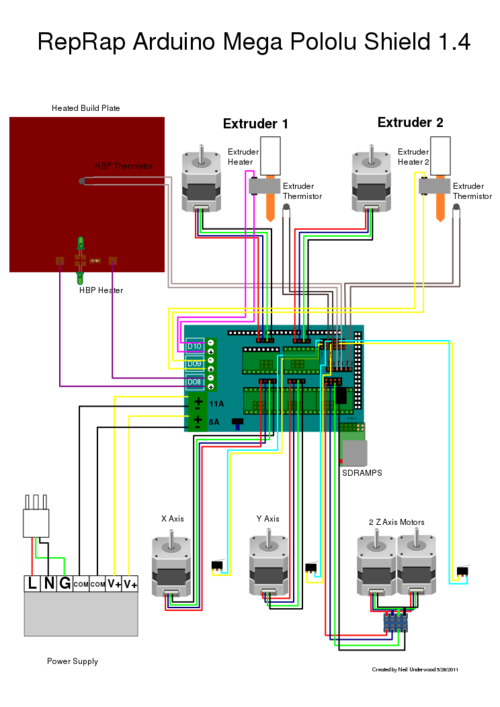
Now that I got over those quirks, wiring them up is a little more straightforward. This image from RepRap says it all:
Next part will be the power supply. Stay tuned!

To make it easy to follow this series, the links are here:

Saturday, March 29, 2014

Creating a 2-Player Blender Game

I've played around with blender a bit and while my favorite is still VFX, I wanted to explore other things it can do. This time, I created a game. To keep it simple yet challenging, I made a 2-player football game.

My son has a stuffed toy he's really fond of so I based my game character on it.
Droozy
The character is quite simple so it was relatively easy to model. I got distracted for a while because I enjoyed recreating the fur using particles and rendering in cycles but after a while, I decided to remove the textures and particles of the character in the game.
Modeled Droozy 
Unlike the robot I used in my previous video which came from blendswap, I needed to rig the character myself.  With the help of the awesome people on the net, I was able to rig my character and got it ready to be animated.
Rigged Droozy
As it is, I can use it to composite a Ted-type movie effect which I plan to do later on but right now, let's get it to play some football.  I animated a run cycle that will loop to simulate a running character. Once I got that working, I added the other elements like the goal, ball, field, and set the properties.  Without any programming, I got the keyboard input to control my character.

I was going for a split screen view which took a bit more research.  Each player has a camera assigned and will follow them as they move around.  I found a viewport.py script that does just what I needed. It was just a copy-paste effort and I didn't need to touch the code itself so non programmers will still be able to follow along the tutorials.

To keep it simple, I didn't implement a scoring mechanism but I added some effect whenever someone makes a goal. After which, the game can be reset by pressing "N".  Here's a video of the game.  I recorded it using camstudio so the frame rate isn't that high.


Seeing the priceless look on my son's face after showing him his favorite stuffed toy come alive in the game,  makes all the trouble worthwhile. =)

Friday, March 14, 2014

3D Scanning Methods Compared

3D Scanning Fever


It will be a while before I can afford a 3d printer but I am already exploring what else I can do with it.  I find it to be most useful in replacing broken parts around the house - I just lost count of the times when I wished I had a 3d printer to fix or fabricate things.  But I'm pretty sure there's a lot more I can do with it. I want 3D printer so bad that I am even justifying its cost as being economical than shopping for Christmas presents. :)

Anyway, since I won't have it anytime soon, I started to explore 3D scanning. Being in a third world country, I tried looking for any do-it-yourself projects or open-source application associated to 3D scanning. To my surprise, not only did I learn that there are quite a few of them around, they have also been around for quite some time.  I thought 3D scanning have just been invented recently. What rock have I been living under?

So, I got very excited and tried almost everything I can get my hands on.  Among the 3D scanning solutions out there, here's what I've tried:
  • Laser
  • Structured light 
  • Photogrammetry or Structure from Motion
Again, the objective was to scan things in 3D with parts I already have lying around. Did I mention how excited I was? Well, let me tell you now that things didn't always work the way I thought it would. All the frustrations were mostly due to the quality of the materials I used but since I'm out of job right now, I want to spend as close to zero as possible so I really pushed things to the edge on this quest.

Laser scanning


What seemed to be a popular in the search engines was DAVID laser scanner. The trial version allows saving of a single scan. It was still a good thing to try since the version as of March 2014 also allowed for structured light (we'll get into this later).

To test DAVID's software, I needed a video or webcam (check!), a calibration board (I printed it out) and a line laser which I didn't have.  I rummaged through some old stuff and found a pen with a laser pointer. It still worked but the battery was weak.  The battery must have leaked since I couldn't open it so I just broke it open to get the guts out.  Yes, that was how excited I was!


Oh, but I needed a line laser.  I googled a bit and found out I can make it a line by getting it through a clear rod. I settled for a piece of clear glue stick. Far from perfect but it was the only thing I could find. Line laser - check! 

DAVID laser scanner

First, the software - DAVID's software was very very easy to work with and will get you scanning fast. It has everything you need for the workflow.  From scanning, mesh adjustment (it already gives you a mesh so you don't need to do that yourself) and merging the scans.  It also gives you feedback when there's something wrong with the scanning process so you can correct it.

One advantage of the hand-held setup was that you can run the laser from different angles allowing you to cover a lot surface on just a single scan. However, I found it very difficult to merge scans using the built-in Shape Fusion tool.  Even the contact pair selection method didn't give me a good merge since you can only select a pair of points to connect unlike Meshlab which asks for 4 pairs of points. The scans I ended up with didn't all match perfectly which is probably due to not having an accurate calibration.  It says that the calibration board must be precisely 90 degrees.  Mine was probably off a few degrees causing some skewing.  Scan after scan after scan, my ghetto line laser just isn't giving me a nice clean, thin line. The sample video provided in their website gave me a clean mesh though.

The issues were probably due to the following so if you want to make this work well, here are some pointers:
  • Use a real line laser - It would have given me a lot better mesh if I did have a real line laser
  • Camera setting -You should be able to set your camera to show only the thin line of the laser.  If you can't do this or do not know how to do it, expect a lot of frustrations.  You will spend a lot of time cleaning up the noise in your scans and the time spent won't be worth it.
  • Take time to build your calibration board carefully 
I can see it working well with the right equipment but after a few days playing around with my ghetto setup, I gave up. I will get a line laser and test it again.

MakerScanner

The only open source scanner I found was MakerScanner. This does not need calibration but the placement of the camera relative to the laser should be precise because it is hard coded in the software and it is part of the calculation of the 3D points.  Hans offered a better alternative so that you can set the distance between the laser and camera but there was no binary format so I wasn't able to try it.

The software is pretty simple and easy to use. The software gives you a colored point cloud. It doesn't have a built-in mesh viewer, mesh reconstruction or merging feature.  Not a problem since you can do all that in Meshlab.  Again, I suffered from the same frustrations related to not having a real line laser so I'm setting it aside until I get a line laser.  Based on my experience, I think MakerScanner right now is okay for single scans since clean-up and merging is a little too tedious. I'll try it out again when I get a line laser.

Structured Light Scanning


I happen to have a pocket projector with a busted power supply. I remedied this by hooking it up directly to a 12V lead acid battery.  I was afraid I might fry my projector so I soldered a 2A glass fuse in-line. Projector - check!
This type of scanning makes use of different patters of lines to make out the shape of the object instead of a single line from a laser. 

DAVID scanner

The same DAVID laser scanner software can also do structured light setup. The good thing about this setup was that you can remove the calibration board after the actual calibration so it doesn't get in the way while scanning.  Also, a single scan took only a few seconds and that already includes the texture. What's not good about it was that scans seemed too shallow (see picture below) compared to laser scanning.  It only captures what is almost directly facing the camera.  This means you have to make more scans around the item and a lot of merging to do to complete the whole mesh. A high resolution projector and camera will of course improve the output.
 

Similar to my experience with the laser method, there was some skewing which I couldn't figure out why. Maybe it has to do with calibration.  In addition, my success was prevented by a noisy line from the projector. The lines have jagged edges which translated into noisy meshes that was hard to clean up.


Overall, the workflow is a little faster compared to laser scanning but it also took a lot more scans.

Brown University - 3D Scanning Software

The only open-source structured light scanner I found was that of Brown University called 3D Scanning Software.  It is very similar to DAVID and uses a checkerboard pattern to calibrate the camera. I just find it harder to calibrate for some reason.  Another difference is that the 3D Scanning Software outputs a point cloud which you can manually convert to a mesh and stitch together using Meshlab.  Still, it suffers from the problem of giving out shallow scans based on my experience.

Photogrammetry or Structure from Motion


Among the 3D scanning methods, I found this to be the easiest and enjoyable. It took very little effort on my part and all the heavy-lifting was done by the software so a modern PC, GPU, and lots of RAM will give the best experience. All I needed to do was take pictures of the subject from different angles, making sure there's a good overlap between the surfaces for the software to figure out how to put it together. The time it takes to process the files depends on the size of each picture, amount of detail in it, and how many pictures there are to be processed.  Ironically, my experience suggests that the more detailed the pictures are, the faster the processing becomes.


The photogrammetry software I've tried were Python Photogrammetry Toolbox (or PPT), which is console based, and VisualSFM which offers a GUI but very similar to the former.  I find VisualSFM faster in terms of processing. Here is an illustration of a typical workflow when reconstructing in VisualSFM:

From pictures to sparse cloud to dense cloud

Both PPT and VisualSFM gives you a dense cloud of points that you can convert into mesh using Meshlab. With less than 50 pictures, I was able to get a detailed reconstruction of the gazelle which was only around 6 centimeters long.

To get a clean output, some commercial software like Agisoft's Photoscan allow you to mask the objects in the pictures to ignore the background. You can also use an image editor to cut out the background before you feed them into the software but that will take time so I tried feeding the same set of raw pictures to both VisualSFM and Photoscan to see how each of them will handle the noise.
Raw input picture

With the camera fixed, the input pictures were taken with the gazelle on top of a tripod, using it as a turntable. The background was not completely covered from side to side as you can see from the picture.  Here is a side-by-side comparison of the dense cloud output from both software:
Left: VisualSFM/ Right: Photoscan
As you can see, VisualSFM pretty much guessed where the edge of the wall was so it was easier to clean up because the points are away from the subject.  Photoscan on the other hand, had the points very close to the subject itself making it very hard to remove.  Something for Photoscan users to remember - mask out the background first before feeding in the pictures.


The following are some key points for an efficient reconstruction:
  • Uniform light - If the object is small, you can probably use a tent softbox. Avoid any shadows. If the object is big, take pictures out on a cloudy day.
  • Sharp pictures - If using a DSLR, set the f-stop as big as it will allow you. Also avoid motion blur so set shutter speed to the fastest your camera allows that will still give you a bright picture.  If scanning a person, make them hold the pose as steady as possible.
  • Overlap - Make sure the outer edges of the pictures overlap that of another picture so that the software can map them well. If using a turntable, make sure the background is either completely black or white and does not have features on it that will confuse the software. Otherwise, you will have  a lot of stray points that you have to clean up
  • Cover the complete area - Feeding more pictures won't necessarily give you a better reconstruction. It's better to give only enough pictures to cover the surface area of the subject being scanned

Overall, I had the most fun reconstructing a 3D model using photogrammetry than any other methods I've tried. Given that you won't be able to get away with some cleaning up of stray vertices (which applies to all methods), it was still the simplest, easiest, and gives the best looking output. I'm not saying this method is the panacea of 3D scanning. Reconstructing models like Yoshi didn't work well since the surface is pretty flat and not enough features can be extracted from it.  I'm pretty sure there's a space for all of these 3D scanning methods depending on one's budget and application.  Here's a breakdown of how I see each method being more effective than the others.


3D Scanning Methods Compared


  • Laser 
    • Best if accuracy is needed and scanning big, static items and spaces  
    • Not safe for face scans without closing eyes or wearing eye protection
  • Structured light 
    • Best for use on simple, shallow, solid, opaque and plain items that do not have enough features or marks on it.  If this is your only option, find a way to coat the item to be scanned with a matte finish. Safe for scanning faces.
    • Not good for dark colored, translucent, reflective and very deep items
  • Photogrammetry 
    • Best if subject has a lot of features or texture
    • Very dependent on the quality of the pictures like motion blur, sharpness, depth of field, exposure, lighting, etc.

 Now, I think I'm enjoying my son's toys more than he does :)
Pictures used to reconstruct this came from frames of a video

Reconstructed using only 36 images that are about 7 megapixels each